- Home
- Products
- Summary & Overview
- Bus Analyzer
- Interface Cards
- FireRepeater
- Connectivity
- IP Cores
- Software
- Accessories
- Solutions
- Support
- News
- Contact
- Company
- Mil1394
- Sitemap
- Search
In the second half of 2010 an Aerospace and Defense (A&D) program reported a signaling level disconnect in the 1394 bus topology which appeared to be triggered by EMI event(s). The point of disconnect wasn’t at the EMI injection point but rather it appeared a few device hops away. The investigation into this issue began around October of 2010. With no adequate instrumentation for the 1394b signal level existing in the market place, DapTechnology developed the 1394b Symbol Recorder module for the FireStealth non-intrusive bus analyzer. Eventually, this tool allowed to pin-point the issue.
In late 2011 and early 2012 DapTechnology had to conclude that he cause of disconnect ought to be a digital logic issue having to do with tightly spaced bus resets rather than a signaling issue. Based on this hypotheses, over the next month, DapTechnology was able to consistently reproduce the issue and determined that a series of four non-completing bus resets in a sequence causes a disconnect to occur 3 hops away from the originator of the bus reset.
Furthermore DapTechnology ran tests on its own FireCore™ beta (1394b) PHY implementation and found very similar results to the Texas Instruments silicon currently used in various aerospace programs. Since two independently designed implementations exhibited similar behavior DapTechnology began to look at the IEEE-1394 standard for clues. Using DapTechnology’s PHY Simulation Environment, which runs the actual C-code from the IEEE-1394-2008 specification, DapTechnology began running simulations to try and recreate the behavior. In parallel, DapTechnology continued to run tests on FireCore while monitoring internal signals. It was through this effort that the root cause of the behavior was determined to be a feature defined in the IEEE-1394-2008 specification itself. It is important to note that the Texas Instruments (TI) TSB41BA3 and TSB81BA3 PHYs do not behave exactly as specified by the standard and this non-standard behavior has been confirmed by TI.
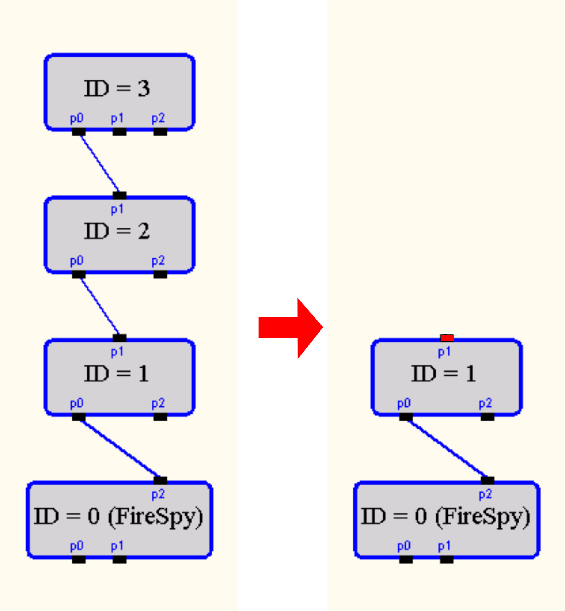
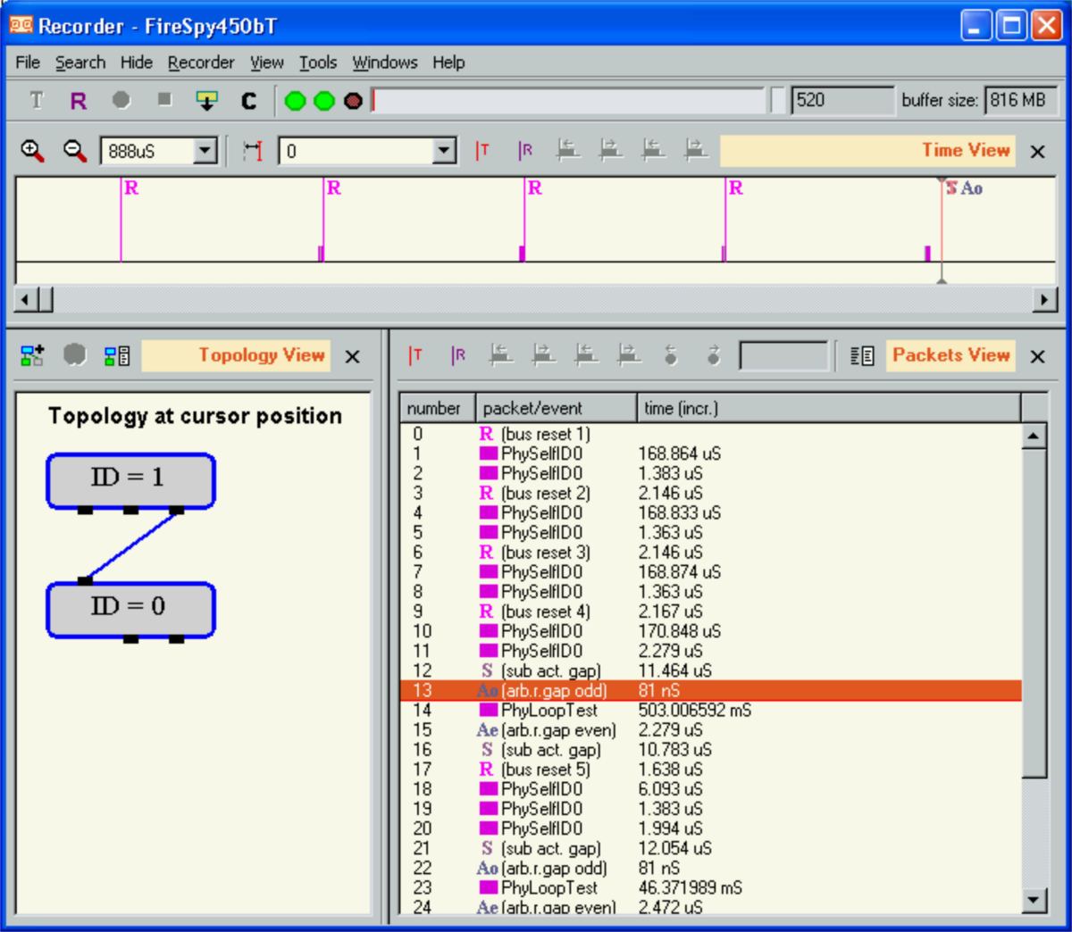
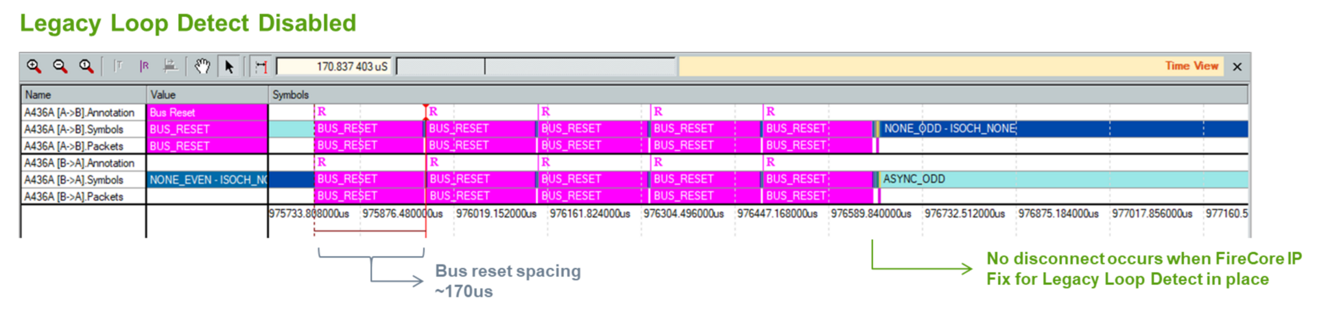
The recording shown on the right is a result of sending four (4) tightly spaced bus resets in a row with a leaf node root and the other leaf node issuing the bus resets.
The recording shows a disconnect/reconnect, that is received after ~500ms which indicates there was a disconnect/reconnect. With this topology and bus reset rate, the erroneous behavior was highly reproducible. If the bus resets are spaced further apart so that each bus reset process completes before the next one begins then no disconnects are observed.
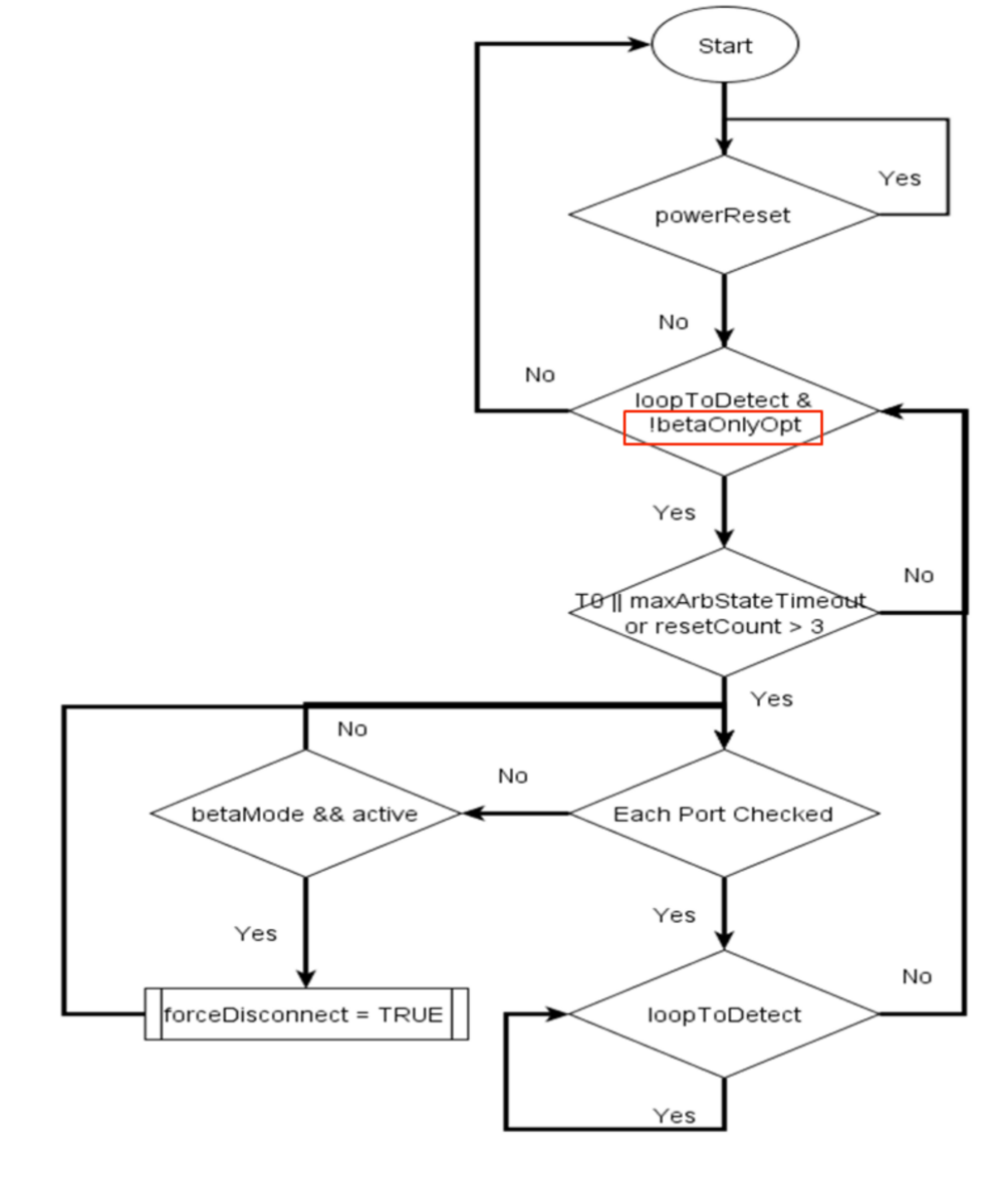
IEEE-1394-2008 section “14.7.13 Loop detection during bus initialization” describes the following behavior.Some loop conditions may be detected during bus initialization. Three conditions are explicitly treated:
If any of these events occur, all Beta ports are forced to commence retraining by ceasing to signal for long enough to appear disconnected and then restarting as if a new connection had been made. They enter the P11: Untested state and a loop-free build is done. A peer port treats loss of synchronization prior to entering the S1: Self-ID Grant or S2: Self-ID Receive state as an indication to move into the P11: Untested state. In the case of condition a, it may now be possible for the tree identify process to complete normally (i.e., there is no need to restart the bus reset process). A Beta-only PHY may begin loop-free build on each port as it completes training. A border PHY, however, may not begin testing any of its Beta ports until the tree identify process completes on all Alpha ports.
While waiting for the tree identify process to complete on active Alpha ports, the Beta ports on a border node shall complete training and enter the P11: Untested state, but shall not send an LTS. This prevents any attached Beta node from making its connection to this border node as a test port and trying to do an attach. The result is that the border node will not be attached to the Beta cloud until the tree identify process has successfully completed on the Alpha ports that are participating in tree identification. When the tree identify process on the Alpha ports has completed, LTS is sent on the Beta ports and a loop-free build is completed on the border node.
To make things worse, TI’s TSB41BA3 device does not implement the standard correctly in such a way that the disconnect occurs more easily the larger the topology
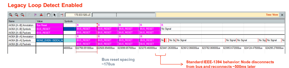
The above transition in a disconnected state can be avoided by turning off the Loop detect mechanism. The image on the right demonstrates that the transition does not happen if the Loop Detect is disabled.
As implied in IEEE-1394-2008 section “14.7.13 Loop detection during bus initialization” this process was defined to keep Legacy loops, which cause continuous bus resets, from disturbing Beta clouds which can detect and resolve loops. However, an all Beta network may also see tightly spaced bus resets at power-up or during EMI events, thereby causing the same process to be executed. Fortunately, in an all Beta network the port doesn’t stay in the LoopDisabled state rather it reconnects and becomes operational again about 500msec after the fourth bus reset. While the 500msec reconnect time isn’t ideal, it is better than staying the LoopDisabled state.
Increasing the T0 timeout (CONFIG_ TIMEOUT time of 166.9µsec) decreases the probability any of these methods would erroneously detect a Legacy loop.
Furthermore, for implementations that can guarantee Legacy loop disconnects are impossible, disabling all three Legacy loop detection methods can provide additional robustness.
User-configurable setting(s) to allow disabling the Legacy Loop Detect mechanism provide(s) for more robust Beta loop node operation during high frequency bus resets
Number: US9,602,302 / US9,882,739 (divisional)
Assignee: DapHolding B.V. (parent company of DapTechnology B.V.)
FilingDate: 2014-06-17 / 2016-08-30
GrantDate: 2016-12-22 / 2018-01-30
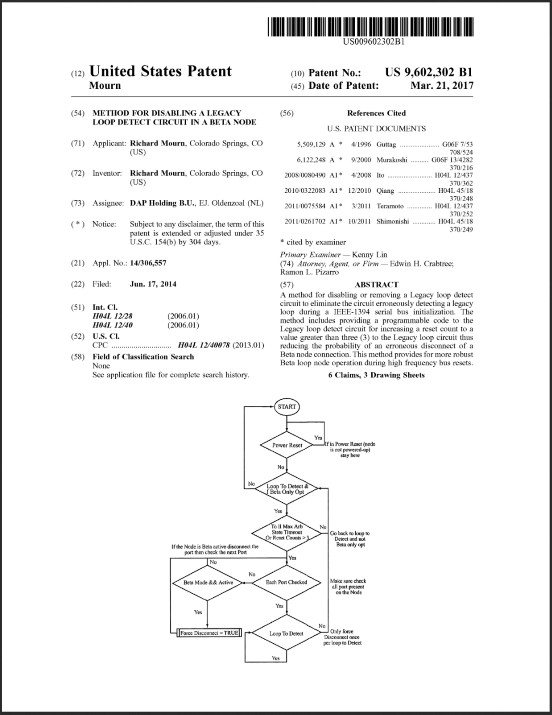
A method for disabling or removing a Legacy loop detect circuit to eliminate the circuit erroneously detecting a legacy loop during a IEEE-1394 serial bus initialization. The method includes providing a programmable code to the Legacy loop detect circuit for increasing a reset count to a value greater than three (3) to the Legacy loop circuit thus reducing the probability of an erroneous disconnect of a Beta node connection.
It is in DapTechnology's core interest to dive forward IEEE-1394 and AS5643 technologies. We invite all interested parties to engage into licensing discussions and ensure a more stable future for the technologies.